Street Lighting Control System- SLC 2.
Features
|
Type of used LEDs. |
Led 35R 241 -40W 3300Lm Rommtech 3S (BG) Led 60R 2x241 -80W 6600Lm Rommtech 3S (BG) |
|
Number of LED lamps into one street lighting WLAN. |
1-100 |
|
Number of WLANs supported
by SLC 2. |
1-255 |
|
Number of Coordinators in one WLAN. |
1 |
|
Number of Routers in one WLAN. |
1-100, by
one for each LED lamp. |
|
Used interface and stack of WLAN. |
2.44 MHz, JenNet/JenNet IP6/802-15. |
|
Type of the communications into WLAN. |
Routing of the messages between the Routers and Coordinator. |
|
WLAN topology. |
Tree
topology with program control of it structure. |
|
Maximal distance between two neighbour lamps in
WLAN. |
80 m. (60 m nominally). |
|
WLAN data traffic speed. |
250 Kb/s |
|
LED lamps control. |
Into each of LED lamps is embedded one Router, working as WLAN device and LEDs controller. The last controls the lighting using PWM (10-90%). Additionally is monitoring and controlling of the voltage, lamp face temperature and others lamp parameters. |
|
Technological program language for LED lamps control. |
Program control language, having 52 types of instructions is used for programming of individual and group LED lamp work applications. The language
instructions are generating from Coordinator and sending to the Routers for
execution. After each execution the Routers return report to the Coordinator.
The last is resending these reports to the Operation station connected to
him. If the Coordinator isn’t connected to any station, it doesn’t resend the
messages but continues to communicate with WLAN Routers. |
|
Monitoring
of WLAN and LED lamp parameters. |
The Routers forms periodically messages of the
states of their LED lamps. These messages are routing on the WLAN and
receiving from Coordinator. The last is sending they
by USB to local operation station (LOS) or by GPRS to the server into Main
Operation Station (MOS), where they are monitoring and saving into the
archive. |
|
Autonomous mode of working of the
Street Lighting WLAN. |
When the Coordinator is disconnected logically or physically from the operation stations, it has ability to control the
WLAN in autonomous mode. This is the case when it has in his eeprom memory saved recipe program, sent before
disconnecting. This program determinates the working modes of LED lamps. It
is cyclic and is active each day to the next connection, reloading or
removing. After
connection to any operation station, the Coordinator recipe can be change. |
|
Control of switching of power supply
of Street Lighting WLAN. |
The switching of power supply of the Street Lighting WLAN is controlling by the WLAN Coordinator. It is every
time supplied. When it is in autonomous mode and has saved recipe, the recipe
determinates when to be switched “on” or “off” of WLAN power supply. This is doing by contactor controlled by
Coordinator. At the moment of activating of power supply, the Coordinator is
starting building of WLAN, searching for its LED lamp Routers. Each WLAN has unique address -number and the recipes generated
in the operation stations are indexed (into recipe DTBS) by this number. |
|
Control by USB. |
The Coordinator of WLAN has embedded USB. By it is possible direct connection of LOS to WLAN and full
control of concrete Street Lighting line. |
|
Measuring of the consummation of LED lamp WLAN. |
The Coordinator makes periodically measurements of
electrical consummation of Street Lighting line. After measurements it sends
corresponded messages to operation station connected to it. For measurement
the Coordinator uses special energy meter, connected by RS 485. |
|
Operation stations. |
There are designed two types operation stations- MOS (Main Operation Station) and LOS(Local Operation Station). The second of them is purpose for individual control of Street Light Control WLAN, using USB Coordinator connection. First (MOS) controls groups of WLANs and functioning as control centre. It uses Internet TCP for connection to the Coordinator of WLANs. Each of
Coordinators has embedded GPRS modem and makes an attempt each 3 minutes to
connect to MOS. If this action is successful it creates socket for
communication with MOS. When MOS has received a request for connection it has
ability for enable this connection or cancel it. The solution is making based
on selected from operator address-number of WLAN. If the request is enabled
MOS begins communication session with the Coordinator of WLAN and direct
control on this network. If the request was cancelled Coordinator tries to connect
with MOS after interval of 3 minutes. |
|
Crypting. |
SLC2 uses three levels of information crypting: - The messages into WLAN are protected with 128 bits switch, using AES. - The
messages between MOS and Coordinator of WLAN are protected with 64 bits
switch, using DES. - The messages between MOS and Remote Computer are
protected by standard protect mechanism. |
|
Remote control. |
SLC2 offers an option of remote control from external Internet computer. In MOS is embedded server accessed
from external client with corresponded rights. The Client has ability to select address number of the
WLAN, program recipe for this WLAN for autonomous mode of working, monitor
the messages of WLAN for time interval and close his connection. During
connection time MOS functions as gateway between the remote client and WLAN. |
Fig.1. Architecture
of Street Light Control System SLC-2.
COORDINATOR
FEATURES:
COMMUNICATOR:
|
Processor |
JN5168-001 32 bits,
32 MHz, RISC |
|
Interfaces |
RS232C/GPRS( TCP ) USB 2.0 Wireless LAN SPI SPI0 - with
integrated 128 KB FLASH SPI1 – internal
unit SPI2 – with 64MB
onboard FLASH |
|
Timers |
3 16 bits
programmable timers 24 bits
programmable timer |
|
Memory |
128 KB fast
memory RAM 128 KB self-contained
FLASH 64MB self-contained
FLASH |
|
Accessories |
Integrated in
communication infrastructure modules (2.4 GHz) GPRS\TCP modem
SIM900 |
|
Power supply |
5V DC |
|
Accessories |
Integrated in
communication infrastructure modules (2.4 GHz) GPRS\TCP modem SIM900 |
PROCESS UNIT:
|
Processor |
ATXmega32A4 8/16 bits, 32
MHz, RISC |
|
Interfaces |
RS485 ( RS485+) Wireless 433MHz LAN (SIM20) Wire Bus (2 Independent highways to access
remote sensors for measurement of temperature and humidity) |
|
Timers |
2 16 bits
programmable timers |
|
Relay outputs |
5 pieces for
external circuits control (~220V) |
|
Accessories |
unit
1-wire bus thermometer DS1823 unit
1-wire bus smart sensor for measuring temperature, humidity and 5 opto uncoupled digital inputs. 1-wire bus
clock-calendar ds1921. Electrical Power Meter of street
line consummation (connected to Coordinator by RS485). Contactor for switching of the
street lighting line current. |
|
Power supply |
12-24V DC ( supplies also the
Communicator ). |
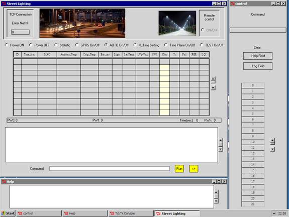
Fig. 3 Graphical User Interface of MOS.
Advantages of used LED LAMPS